- Get link
- X
- Other Apps
Full wave rectifiers have some fundamental advantages over their half wave rectifier counterparts. The full wave rectification can be done by the following methods.

Solved Centre Tapped Transformer 12 Vac Mains 240 Vac 50
In A Bridge Rectifier Circuit What Happens If One Of The

Rectifier Wikipedia
Rectifier circuit has at the input side a transformer xformer.

Draw the circuit diagram of bridge rectifier. Full wave rectifier full wave rectifier circuit with working. A full wave rectifier is a circuit arrangement which makes use of both half cycles of input alternating current ac and converts them to direct current dc. Center tapped full wave rectifier.
In some cases a resistor capacitor coupled filter rc is also used. Another type of circuit that produces the same output waveform as the full wave rectifier circuit above is that of the full wave bridge rectifier. But youll gain much if you draw the circuit following the verbal instructions i.
Bridge rectifier using four diodes if two branches of a circuit is connected by a third branch to form a loop then the network is called a bridge circuitout of these two the preferable type is bridge rectifier circuit using four diodes because the two diode type requires a center tapped. The bridge rectifier is widely used to provide full wave rectification and it is possibly the most widely used circuit for this. The average dc output voltage is higher than for half wave rectifier the output of the full wave rectifier has much less ripple than that of the half wave rectifier producing a smoother output waveform.
Choosing a particular diode or any other switching device for a corresponding rectifier needs some considerations of the device like peak inverse voltage piv forward current if voltage ratings etc. It contains four diodes arranged in a bridge format and an ordinary step down transformer. This type of single phase rectifier uses four individual rectifying diodes connected in a closed loop bridge configuration to produce the desired output.
I had to do this without a circuit diagram. The circuit diagram below shows a half wave rectifier with capacitor filter. Bridge rectifier circuit diagram next stage is a diode bridge rectifier which uses four or more diodes depending on the type of bridge rectifier.
Using four diodes the bridge rectifier the circuit has a distinctive format with the circuit diagram based on a square with one diode on each leg. The average dc output voltage is higher than for half wave the output of the full wave rectifier has less ripple than that of half wave rectifier generating a smoother output wave form. Full wave bridge rectifier circuit diagram is widely used in ac to dc converter and dc circuit designs this full wave rectifier called as bridge rectifier due to it shape.
A circuit diagram of full wave rectifier with capacitor filter will be shown later. We can make the output of half wave rectifier smooth by using a filter a capacitor filter or an inductor filter across the diode. Draw the circuit diagram of four diode full wave bridge rectifier explain its operation.
In our tutorial on half wave rectifiers we have seen that a half wave rectifier makes use of only one half cycle of the input alternating current.

Bridge Rectifier Circuit Theory With Working Operation

138 C Draw The Circuit Diagram Of A Full Wave Br

Bridge Rectifier Circuit Design Details Tips

Solved A Draw The Circuit Diagram Of A Full Bridge Rect

Full Wave Bridge Rectifier Circuit Diagram Easyeda

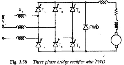
Bridge Rectifier Circuit Diagram With Freewheeling Diode

Smoothing Cap Vs Filter For Full Wave Bridge Rectifier

Full Wave Rectifier Bridge Rectifier Circuit Diagram With

Solved Draw The Circuit Diagram For A Bridge Rectifier Ci

Full Wave Bridge Rectifier Operation With Capacitor Filter
Silicon Bridge Full Wave Rectifier Testing
Ac Power Supply Transformer And Bridge Rectifier Circuitlab
draw the circuit diagram of bridge rectifier
draw the circuit diagram of bridge rectifier and explain its operation
draw the circuit diagram of bridge rectifier and explain its working
- Get link
- X
- Other Apps
Comments
Post a Comment